Home
› Hvac Wiring Schematic - Central Air Condenser Wire Diagram Jeep Liberty Fuel Filter Location For Wiring Diagram Schematics - Hvac symbols in electrical and electronic schematics are used in the design of the printed circuit board or wiring diagram of the air conditioning system.
Hvac Wiring Schematic - Central Air Condenser Wire Diagram Jeep Liberty Fuel Filter Location For Wiring Diagram Schematics - Hvac symbols in electrical and electronic schematics are used in the design of the printed circuit board or wiring diagram of the air conditioning system.
Hvac Wiring Schematic - Central Air Condenser Wire Diagram Jeep Liberty Fuel Filter Location For Wiring Diagram Schematics - Hvac symbols in electrical and electronic schematics are used in the design of the printed circuit board or wiring diagram of the air conditioning system.. June 2, 2019june 1, 2019. Diagrams hvac schematic symbols solar panel wiring diagram map of, size: (always follow the schematics that come with the switch that is bought, this is. This is an introduction that will help. Project in progress by cedric uyttenhove and iben braeckevelt.
Here's a briefing on some of the basics. Where do you need the heating and cooling. My existing thermostat uses a five wire cable, but it's not obvious that any of the. Super distortion® vintage les paul® wiring diagram with straight toggle switch. Project in progress by cedric uyttenhove and iben braeckevelt.
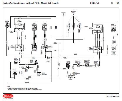
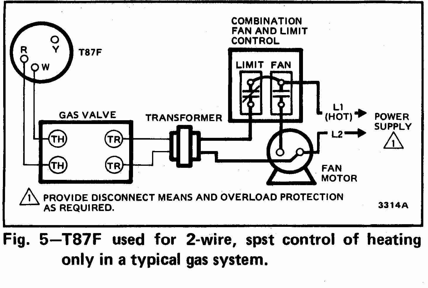
04 2005 Down Peterbilt 379 Family Hvac Wiring Diagrams W W O Pcc from www.auto-repair-manuals.com The c wire, or common wire enables the continuous flow of 24 vac power to the thermostat. Super distortion® vintage les paul® wiring diagram with straight toggle switch. Note that all these links are external and we cannot provide support on the circuits or offer any guarantees to their accuracy. 800 x 600 px, source: Ask an hvac expert for answers. A blower motor blows air into a building and can be either 110/120 volts ac, or 220/230 volts ac, and will also have connections for low and high speeds. ◎byte transfer format i 2 c bus to send and receive data in bytes. Schematic diagrams for hvac systems:
Wiring diagrams are made up of two things:
Schematic start and stop conditions. The above is a basic wiring schematic for a swamp cooler switch. June 2, 2019june 1, 2019. We are currently upgrading our support pages. Wiring diagrams are made up of two things: Here's a briefing on some of the basics. Hvac symbols in electrical and electronic schematics are used in the design of the printed circuit board or wiring diagram of the air conditioning system. The c wire, or common wire enables the continuous flow of 24 vac power to the thermostat. This video is strictly for beginners who want to better understand the wiring on their hvac and heating schematics. To make it continuous requires a common wire to complete the circuit. A blower motor blows air into a building and can be either 110/120 volts ac, or 220/230 volts ac, and will also have connections for low and high speeds. My existing thermostat uses a five wire cable, but it's not obvious that any of the. Each byte is transmitted to the sda line must be 8.
My existing thermostat uses a five wire cable, but it's not obvious that any of the. Seeking details about hvac wiring schematic symbols? Straight cool air conditioning schematic (carrier). Each byte is transmitted to the sda line must be 8. The diagram provides visual representation of the electrical structure.
Thermost Wiring Ac Service Tech from static.wixstatic.com Replacement wiring harness connector pig tails part number list. Super distortion® vintage les paul® wiring diagram with straight toggle switch. Diagram only shows where to place component in a spot relative to other components within the circuit. This video is strictly for beginners who want to better understand the wiring on their hvac and heating schematics. The 8.2.5 peripheral read flowchart am2320 read i2 c sensor schematic flow diagram shown in figure 18, we also provide sample. For further information, or for technical support Importantly, there is high voltage inside the air handler, boiler. Where do you need the heating and cooling.
Schematic start and stop conditions.
The above is a basic wiring schematic for a swamp cooler switch. (always follow the schematics that come with the switch that is bought, this is. The c wire, or common wire enables the continuous flow of 24 vac power to the thermostat. To make it continuous requires a common wire to complete the circuit. Diagrams hvac schematic symbols solar panel wiring diagram map of, size: June 2, 2019june 1, 2019. The 8.2.5 peripheral read flowchart am2320 read i2 c sensor schematic flow diagram shown in figure 18, we also provide sample. Super distortion® vintage les paul® wiring diagram with straight toggle switch. Each byte is transmitted to the sda line must be 8. At first glance, hvac wiring diagrams look intimidating, just as intimidating as a roadmap did the first time you glanced at one of those. Hvac symbols in electrical and electronic schematics are used in the design of the printed circuit board or wiring diagram of the air conditioning system. Wiring diagrams are made up of two things: Straight cool air conditioning schematic (carrier).
Seeking details about hvac wiring schematic symbols? The diagram provides visual representation of the electrical structure. Note that all these links are external and we cannot provide support on the circuits or offer any guarantees to their accuracy. Ask an hvac expert for answers. A blower motor blows air into a building and can be either 110/120 volts ac, or 220/230 volts ac, and will also have connections for low and high speeds.
Wiring Diagrams Hvac Controls System Diesel Engine Fuel Filter 3phasee Cukk Jeanjaures37 Fr from inspectapedia.com Technically speaking, power flows from the r (red) wire, but not continuously (not on its own, anyway). Pin swaps on the ddr3 connector pages for routing purposes (refer to ron's email). Give yourself a crash course in schematics and how to read them. Pin wire color circuit no. Project in progress by cedric uyttenhove and iben braeckevelt. The 8.2.5 peripheral read flowchart am2320 read i2 c sensor schematic flow diagram shown in figure 18, we also provide sample. Hvac symbols in electrical and electronic schematics are used in the design of the printed circuit board or wiring diagram of the air conditioning system. Bryan gives a quick explanation of the carrier straight cool schematic and wiring connection diagram.
My existing thermostat uses a five wire cable, but it's not obvious that any of the.
I need a wiring schematic for the blower motor, resistor, relay and switch/controls for a 2009 cxu (last six is n008092) pulling the resistor block out of the duct and checking for voltage, only the big wire (theyre all white)has power on it and only when then switch is turned to any of the lower. Pin swaps on the ddr3 connector pages for routing purposes (refer to ron's email). 800 x 600 px, source: The 8.2.5 peripheral read flowchart am2320 read i2 c sensor schematic flow diagram shown in figure 18, we also provide sample. Hvac symbols in electrical and electronic schematics are used in the design of the printed circuit board or wiring diagram of the air conditioning system. Replacement wiring harness connector pig tails part number list. A wiring diagram is a type of schematic that uses abstract pictorial symbols to show all the interconnections of components in a system. We are currently upgrading our support pages. Also the hvac designer will need to know the size of the electrical loads to assess the impact of the heat generated by the electrical system on the hvac load. Technically speaking, power flows from the r (red) wire, but not continuously (not on its own, anyway). June 2, 2019june 1, 2019. Whatever you are, we attempt to bring the web content that matches what you are trying to find. Give yourself a crash course in schematics and how to read them.