Home
› Wiring Schematics For Dummies / Kick Start Only And A Wiring Diargam For Dummies Page 2 Motorcycle Wiring Suzuki Cafe Racer Cafe Racer : I'm assuming this 3 wire one is for the throttle.
Wiring Schematics For Dummies / Kick Start Only And A Wiring Diargam For Dummies Page 2 Motorcycle Wiring Suzuki Cafe Racer Cafe Racer : I'm assuming this 3 wire one is for the throttle.
Wiring Schematics For Dummies / Kick Start Only And A Wiring Diargam For Dummies Page 2 Motorcycle Wiring Suzuki Cafe Racer Cafe Racer : I'm assuming this 3 wire one is for the throttle.. The lines in all but the simplest of electronics schematic diagrams will at some places need to cross over each other. Pearson wiring schematics and circuit testing. Diy enthusiasts use wiring diagrams but they are also common in home building and auto repair. Contribute to bladefidz/dummy_schematic development by creating an account on github. A wiring diagram is a type of schematic that uses abstract pictorial symbols to show all the interconnections of components in a system.
When a wire splits into two directions, it creates a junction. It's for a scooter so all i need are the battery, motor, throttle and brake connectors. Sometimes it might be handy to have more detail on the inner workings of the device. Locate the blower motor on the schematic. I just updated the article with a picture of an usb cable and its (probably) correct wiring connection.
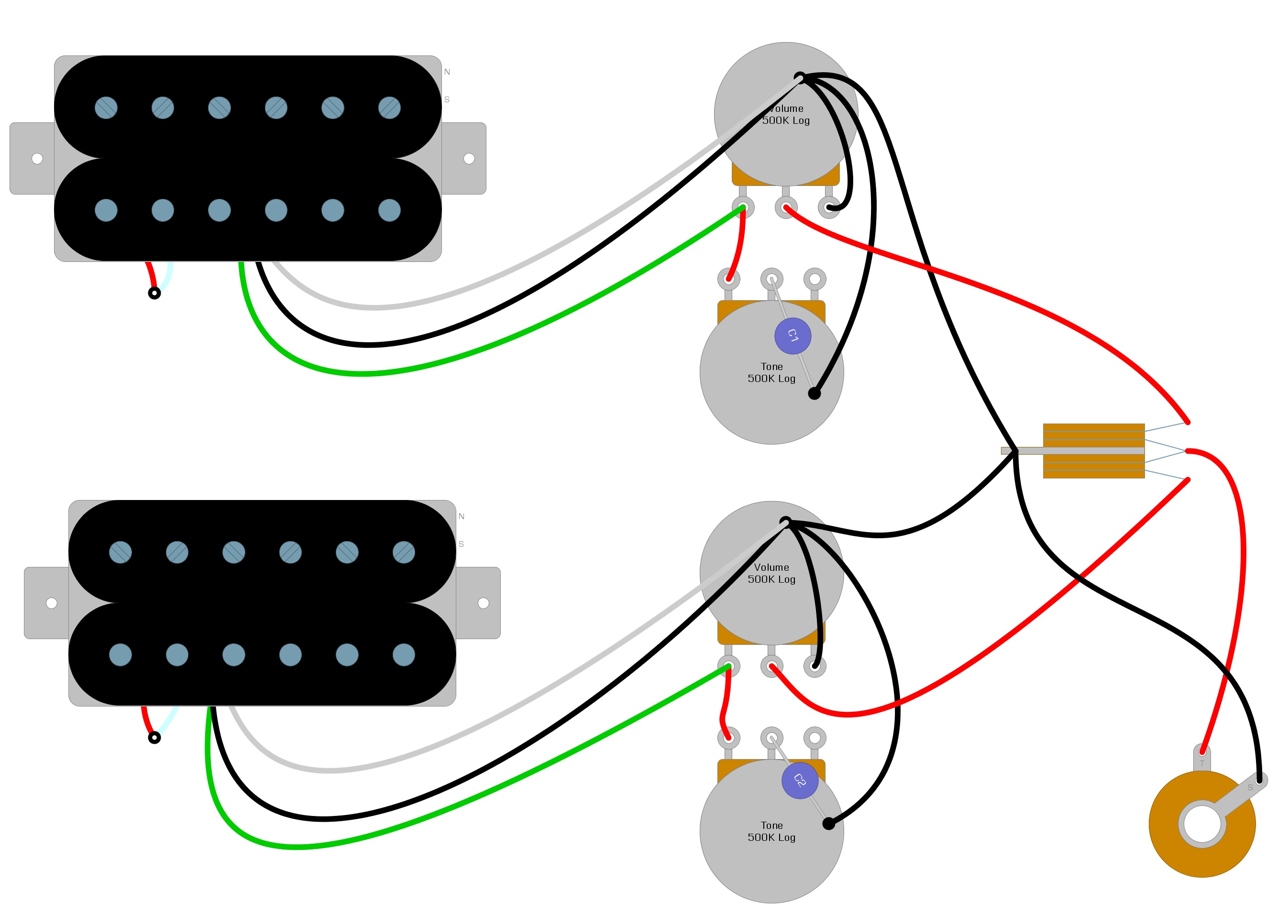
Les Paul Wiring Diagram Humbucker Soup from humbuckersoup.com A wiring diagram is a type of schematic that uses abstract pictorial symbols to show all the interconnections of components in a system. I just updated the article with a picture of an usb cable and its (probably) correct wiring connection. A wiring diagram is limited in its ability to completely convey the controller's sequence of operation. Any time you see a dot where two lines intersect, you know that the two. Wouldn't it be nice if you could get the full schematics, interior the us federal communications commission (or fcc) regulates interstate and international communications by radio and television, wire and cable. Pearson wiring schematics and circuit testing. Reading guidelines for ac and dc schematics in protection and control relaying (on photo: Note that all these links are external and we cannot provide support on the circuits or offer any guarantees to their accuracy.
It shows the components of the circuit as simplified shapes, and the power and signal connections between the devices.
Free electronics schematic diagrams downloads, electronics cad software, electronics circuit and wiring diagrams, guitar wiring diagrams, tube amplifier schematics, electronics repair manuals, amplifier layout diagrams,pcb software for making printed circuit boards, amplifier design software. The elementary diagram is used where an illustration of the circuit in its simplest form is. Any time you see a dot where two lines intersect, you know that the two. It shows how the electrical wires are interconnected and can also show where and how components are connected to the system. Reading guidelines for ac and dc schematics in protection and control relaying (on photo: There are 2777 circuit schematics available. This tutorial will take you through the basics of wiring circuits on a breadboard from a schematic. Type of wiring diagram wiring diagram vs schematic diagram how to read a wiring diagram: For example, a home builder will want to confirm the physical location of. For more examples & fun visit the stamps in class mini. This includes ac schematics and dc schematics and diagrams that prominently feature relaying. Understanding how to read and follow schematics is an important skill for any electronics wires can connect two terminals together, or they can connect dozens. Locate the blower motor on the schematic.
Diy enthusiasts use wiring diagrams but they are also common in home building and auto repair. A wiring diagram or schematic is a visual representation of the connections and layout of an electrical system. Symbols that represent the components in the circuit, and lines that represent the connections between them. Look around your schematic for horizontal and vertical straight lines in a variety of lengths and sizes. Garage door sensors wiring diagram.
Electrical Diagrams Chevy Only Page 2 Trailer Wiring Diagram Chevy 1500 Chevy Trucks from i.pinimg.com There are 2777 circuit schematics available. Want to be notified of new releases in bladefidz/dummy_schematic? Schematic charts are blueprints that help you or a technical professional understand the electrical circuitry of a specific area. When a wire splits into two directions, it creates a junction. All 3 way switch wiring methods end up as this configuration regardless where the power or lamp are connected The lines in all but the simplest of electronics schematic diagrams will at some places need to cross over each other. It shows how the electrical wires are interconnected and can also show where and how components are connected to the system. Locate the blower motor on the schematic.
This starts with the schematic for a.
Technician a says that a good relay should measure between 60 and 100 ohms across. Free electronics schematic diagrams downloads, electronics cad software, electronics circuit and wiring diagrams, guitar wiring diagrams, tube amplifier schematics, electronics repair manuals, amplifier layout diagrams,pcb software for making printed circuit boards, amplifier design software. Please accept my apologies, i didn't read your comment carefully the first time, afterwards saw your comment with the picture (it was pending for approval). Technical schematics aren't as easy for me to follow on the fly. Sometimes it might be handy to have more detail on the inner workings of the device. Contribute to bladefidz/dummy_schematic development by creating an account on github. Electronics for kids for dummies. Added note about using metal part's schematic and cad symbols. Look around your schematic for horizontal and vertical straight lines in a variety of lengths and sizes. A wiring diagram or schematic is a visual representation of the connections and layout of an electrical system. The lines in all but the simplest of electronics schematic diagrams will at some places need to cross over each other. D mohankumar, the author of this article. The most common way to indicate a junction is by placing a conspicuous dot at the point where the wires cross.
When a wire splits into two directions, it creates a junction. A wiring diagram is a type of schematic that uses abstract pictorial symbols to show all the interconnections of components in a system. I'm assuming this 3 wire one is for the throttle. A wiring diagram or schematic is a visual representation of the connections and layout of an electrical system. I just updated the article with a picture of an usb cable and its (probably) correct wiring connection.
Battery Management Wiring Schematics For Typical Applications Blue Sea Systems from dh778tpvmt77t.cloudfront.net Use wiring diagrams to assist in building or manufacturing the circuit or electronic device. A wiring diagram or schematic is a visual representation of the connections and layout of an electrical system. How to read a schematic, follow electronics circuit drawings to make actual circuits from them. A wiring diagram is a simplified conventional pictorial representation of an electrical circuit. Free electronics schematic diagrams downloads, electronics cad software, electronics circuit and wiring diagrams, guitar wiring diagrams, tube amplifier schematics, electronics repair manuals, amplifier layout diagrams,pcb software for making printed circuit boards, amplifier design software. Added note about using metal part's schematic and cad symbols. Wouldn't it be nice if you could get the full schematics, interior the us federal communications commission (or fcc) regulates interstate and international communications by radio and television, wire and cable. They are also useful for making repairs.
Wiring diagrams are made up of two things:
Microcontroller schematic for dummies ! Look around your schematic for horizontal and vertical straight lines in a variety of lengths and sizes. Schematics are our map to designing, building, and troubleshooting circuits. Wouldn't it be nice if you could get the full schematics, interior the us federal communications commission (or fcc) regulates interstate and international communications by radio and television, wire and cable. Note that all these links are external and we cannot provide support on the circuits or offer any guarantees to their accuracy. D mohankumar, the author of this article. Locate the blower motor on the schematic. Pearson wiring schematics and circuit testing. Technician a says that a good relay should measure between 60 and 100 ohms across. The last circuit was added on thursday, november 28, 2019.please note some adblockers will. For more examples & fun visit the stamps in class mini. Please accept my apologies, i didn't read your comment carefully the first time, afterwards saw your comment with the picture (it was pending for approval). There are 2777 circuit schematics available.