4X1 Mux Logic Diagram : Fundamentals of Digital Circuits - Multiplexer circuits 2 1 and 4 1.. As we know a multiplexer has 1 output and 2n where n is the no. How to write 4x1 mux in vhdl xilinx. A transmission gate is an electronic element and good non mechanical relay. Implement a full adder with two 4 x 1 multiplexers. A multiplexer or mux is a combinational circuits that selects several analog or digital input signals and forwards fig.1:
The symbol used in logic diagrams to identify a multiplexer is as follows A transmission gate is an electronic element and good non mechanical relay. In this post, i will tell you what is multiplexer (mux) and i am also will tell you about its working with logic diagram and uses. I have this program i am suppose to make for this diagram 4x2 decoder diagram: The outputs of first stage 4x1 multiplexers are applied as inputs of 2x1 multiplexer that is present in second stage.
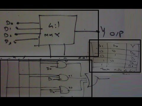
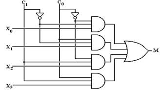
4x1 Mux Logic Diagram - Wiring Diagram Schemas from i.ytimg.com Write a vhdl code to implement 4 x 1 mux using logic gates, if else and with select and simulate the design. 4 x 1 mux using logic gates electronics q a circuitlab. Multiplexers and de multiplexers examradar. The circuit diagram of 4x1 multiplexer is shown in the following figure. Implement a full adder with two 4 x 1 multiplexers. The block diagram of 4x1 multiplexer is shown in the. How do implement an 8:1 line multiplexer using two 4:1 since you have mentioned only 4x1 mux, so lets proceed to the answer. I made it be an xor but you can change the 0 and 1 bits on the data inputs (in00, in01, in10, in11) and make it do whatever.
Multiplexer circuits 2 1 and 4 1.
How do implement an 8:1 line multiplexer using two 4:1 since you have mentioned only 4x1 mux, so lets proceed to the answer. Multiplexer (mux) 2 x 1mux design watch more videos at www.tutorialspoint.com/videotutorials/index.htm lecture by: Multiplexers, or mux's, can be either digital circuits made from high speed logic gates used to switch digital or binary data or they can be analogue types using transistors 4 channel multiplexer using logic gates. The general block level diagram of a multiplexer is shown below. 4 x 1 mux using logic gates electronics q a circuitlab. 4 to 1 multiplexer, multiplexer in digital logic, 4 to 1 multiplexer in hindi multiplexer tutorial, 4:1 multiplexer, multiplexer and. The circuit diagram of 4x1 multiplexer is shown in the following figure. Mux working symbol and logic diagram. The truth table of 4x1 mux is : And finally we have applied output of both 4x1 muxes to an or gate, since at a time only one of the 4x1 mux will activate. 2:1 mux verilog in data flow model is given below. I keep trying to change the initial values of the output array from 0 to 1 and 1 to 0 by just negating them but i still never get the desired result. The schematic diagram, boolean equation and the truth table of a 2:1 design using transmission gate logic.
When a signal takes too long transiting from one logic level to another, a transition violation is reported. How to make 8x1 multiplexer using 2 4x1 multiplexer? A8da3 8 1 mux logic diagram digital resources. Derive the truth table that defines the required relationship problem 7: 4 to 1 multiplexer, multiplexer in digital logic, 4 to 1 multiplexer in hindi multiplexer tutorial, 4:1 multiplexer, multiplexer and.
4x1 Mux Logic Diagram - Wiring Diagram Schemas from www.electronics-tutorial.net · pc with windows xp. You need a combinational logic with 16 input pins, 4 select lines and one output. Multiplexer circuits 2 1 and 4 1. Source code:module fa_mux(sum,cout,a,b,cin);output cout,sum;input a,b,cin;wire cinb;mux m1(.z(sum),.d0(cin),.d1(cinb),.d2(cinb),.d3(cin),.s0(a),.s1(b) documents. How to make 8x1 multiplexer using 2 4x1 multiplexer? The block diagram of 4x1 multiplexer is shown in the. The implementation of not gate is done using n selection lines. A) draw component level logic diagram of a 4x1 mux using 2x1 muxes.
Isnt a mux a logic gate already? When sel is at logic 0 out=i0 and when select is at logic 1 out=i1. A multiplexer or mux is a combinational circuits that selects several analog or digital input signals and forwards fig.1: Mux working symbol and logic diagram. Implement a full adder with two 4 x 1 multiplexers. We can analyze it y = x'.1 + x.0 = x' it is not gate using 2:1 mux. 8 1 mux logic diagram exclusive wiring diagram design. Multiplexer circuits 2 1 and 4 1. We can easily understand the operation of the above circuit. Multiplexer (mux) 2 x 1mux design watch more videos at www.tutorialspoint.com/videotutorials/index.htm lecture by: Multiplexers different ways to implement verilog by examples. Multiplexers and de multiplexers examradar. How to make 8x1 multiplexer using 2 4x1 multiplexer?
The outputs of first stage 4x1 multiplexers are applied as inputs of 2x1 multiplexer that is present in second stage. Write a vhdl code to implement 4 x 1 mux using logic gates, if else and with select and simulate the design. Multiplexers different ways to implement verilog by examples. Multiplexer circuits 2 1 and 4 1. When a signal takes too long transiting from one logic level to another, a transition violation is reported.
How to design a 4 by 1 multiplexer using NAND or NOR gates - Quora from qph.fs.quoracdn.net How to make 8x1 multiplexer using 2 4x1 multiplexer? A multiplexer or mux is a combinational circuits that selects several analog or digital input signals and forwards fig.1: Multiplexers different ways to implement verilog by examples. The block diagram of 4x1 multiplexer is shown in the. A8da3 8 1 mux logic diagram digital resources. Vhdl code of 8x1mux using two 4x1 mux : You need a combinational logic with 16 input pins, 4 select lines and one output. Verilog program not getting desired output on 4x1 mux.
We can analyze it y = x'.1 + x.0 = x' it is not gate using 2:1 mux.
Write a vhdl code to implement 4 x 1 mux using logic gates, if else and with select and simulate the design. Multiplexer can act as universal combinational circuit. Multiplexers different ways to implement verilog by examples. · pc with windows xp. All the standard logic gates can be implemented with multiplexers. 4 x 1 mux using logic gates electronics q a circuitlab. 8 1 mux logic diagram exclusive wiring diagram design. 4 to 1 multiplexer : Hello, can someone please explain me how to design a logic circuit of 4x1 mux using 2x1 muxes and logic gates ? The schematic diagram, boolean equation and the truth table of a 2:1 design using transmission gate logic. The truth table of 4x1 mux is : 4 to 1 multiplexer, multiplexer in digital logic, 4 to 1 multiplexer in hindi multiplexer tutorial, 4:1 multiplexer, multiplexer and. In this post, i will tell you what is multiplexer (mux) and i am also will tell you about its working with logic diagram and uses.