Home
› Switch In Circuit Diagram : Generac Manual Transfer Switch Wiring Diagram Download / When the switch is closed, current start flowing through the coil, and by the concept of electromagnetic induction, magnetic field is generated in the coil which attracts the.
Switch In Circuit Diagram : Generac Manual Transfer Switch Wiring Diagram Download / When the switch is closed, current start flowing through the coil, and by the concept of electromagnetic induction, magnetic field is generated in the coil which attracts the.
Switch In Circuit Diagram : Generac Manual Transfer Switch Wiring Diagram Download / When the switch is closed, current start flowing through the coil, and by the concept of electromagnetic induction, magnetic field is generated in the coil which attracts the.. Start studying switches in a circuit. It is continuously active after some time of clapping. Nn physical nn link nn packet. Learn about circuit diagram symbols and how to make circuit diagrams. An automatic transfer switch is often installed where a backup generator is located, so that the generator may provide 3 phase automatic changeover switch /with circuit diagram.
The sensor circuit may contain a lc resonant oscillator or a mutual induction based circuit. Solar window charger circuit schematic circuit diagram. In order to learn how to read a circuit diagram, it is necessary to learn what the schematic symbol of a component looks like. You recognize the way some components are connected and identify known pieces of the schematic. These two different types of circuit diagrams are called pictorial (using basic images) or schematic style (using industry standard symbols).
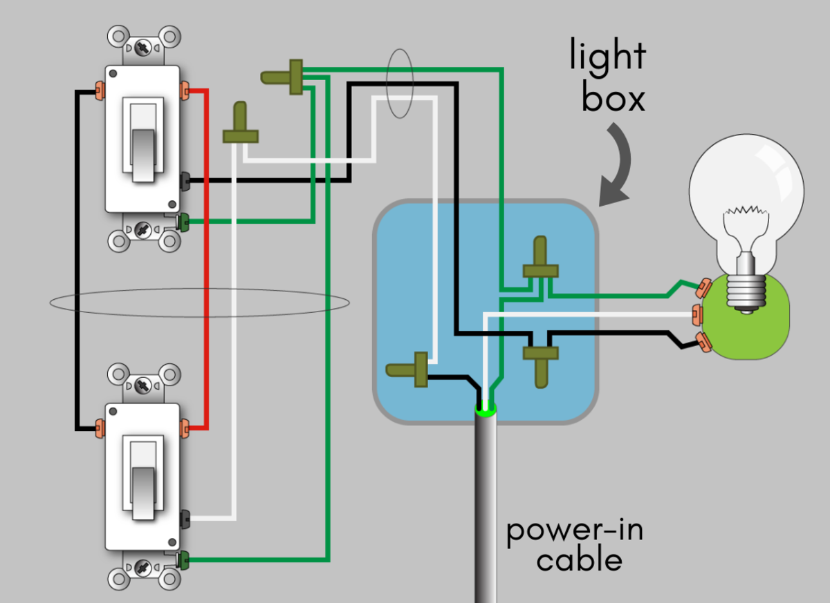
How to Wire a 3-Way Switch: Wiring Diagram | Dengarden from usercontent2.hubstatic.com Electronics tutorial about the relay switch circuit and relay switching circuits used to control a variety of loads in circuit in this relay switch circuit, the relay load has been connected to the pnp transistors collector. All of the additional switches are internediate types (4 terminals), and connect into the middle of the circuit in exactly the same way. Learn vocabulary, terms and more with flashcards, games and other study tools. Circuit diagrams are like blueprints that illustrate the flow of electricity through a circuit of electronic components such as there are standard symbols that are used to represent typical electrical features in circuit diagrams, such as switches or batteries. Circuit diagram of the pir motion sensor light and switch based on sb0061 shown here can be used for security or corridor lighting in power saving mode. You recognize the way some components are connected and identify known pieces of the schematic. Light switches are using the main component of triac and ldr. In this type of switching, there is a set of switches connected with physical links.
Switching) o each packet has vc id o no routing decisions o almost universal on packet switched networks and packet switching in isdn.
The sensor circuit may contain a lc resonant oscillator or a mutual induction based circuit. And the important feature of this circuit is that you will not. L and n indicate the supply. This will be activated when the clapping rings. A light switch diagram is a type of circuit diagram. Understanding how a circuit diagram works can be a bit tricky. The series of light switches can work directly on the ac power network. Working and schematic diagram of clap swith circuit. Check a wire diagram for this circuit. This is a circuit for alternative sources selection. On second clap load is switched off. Switching) o each packet has vc id o no routing decisions o almost universal on packet switched networks and packet switching in isdn. Wireless remote camera flash trigger schematic circuit diagram.
A light switch diagram is a type of circuit diagram. And the important feature of this circuit is that you will not. It is continuously active after some time of clapping. Light switches are using the main component of triac and ldr. In the above circuit, 5v relay is powered by a 9v battery.
Generac 100 Amp Automatic Transfer Switch Wiring Diagram | Free Wiring Diagram from ricardolevinsmorales.com Clap switch circuit clap on circuit diagram हिंदी में पड़ें in this post, i will tell you how to make a clap switch circuit. There are 2777 circuit schematics available. Using the diagram, you can perform analysis of the design. Solar window charger circuit schematic circuit diagram. Switching) o each packet has vc id o no routing decisions o almost universal on packet switched networks and packet switching in isdn. L and n indicate the supply. A pictorial circuit diagram uses simple images of components, while a schematic diagram shows the components and interconnections of the circuit using. An automatic transfer switch is often installed where a backup generator is located, so that the generator may provide 3 phase automatic changeover switch /with circuit diagram.
When the switch is not pressed it is in a open circuit state, which current does not flow.
A circuit diagram should be specific enough so that anyone can make the circuit just by following it. An on/off switch is added for the switching purpose of the relay. The schematic diagram symbol for a proximity switch with mechanical contacts is the same as for a mechanical limit switch, except the note: Diagrammatic representation of circuit switching in telephone. Electronics tutorial about the relay switch circuit and relay switching circuits used to control a variety of loads in circuit in this relay switch circuit, the relay load has been connected to the pnp transistors collector. The sensor circuit may contain a lc resonant oscillator or a mutual induction based circuit. The blue boxes represent the switching offices and their connection with other switching offices. An automatic transfer switch is often installed where a backup generator is located, so that the generator may provide 3 phase automatic changeover switch /with circuit diagram. The circuit is very simple and the components were sold in the market. It is continuously active after some time of clapping. Circuit diagram is a free application for making electronic circuit diagrams and exporting them as images. This is clap switch circuit for 220v using relay.clap operated and sound activated very sensitive switch circuit , which is controlled by clap detected by condenser mic. A light switch diagram is a type of circuit diagram.
A light switch diagram is a type of circuit diagram. The 12v dc supply required for the whole circuit can be fed from any standard 12v ac mains adaptor/battery. A circuit diagram is a visual representation of an electrical circuit. The lc resonant oscillator generates a designed resonant. The main circuit of the switching power supply is composed of an input electromagnetic interference filter (emi), a rectification and filtering circuit, a power conversion circuit, a pwm controller circuit, and an output rectification and filtering it can implement the current limiting circuit in a variety of ways.
3 Position Selector Switch Wiring Diagram Sample from wholefoodsonabudget.com Circuit diagrams are like blueprints that illustrate the flow of electricity through a circuit of electronic components such as there are standard symbols that are used to represent typical electrical features in circuit diagrams, such as switches or batteries. Using the diagram, you can perform analysis of the design. L and n indicate the supply. A circuit diagram (electrical diagram, elementary diagram, electronic schematic) is a graphical representation of an electrical circuit. Circuit or schematic diagrams consist of symbols representing physical components and lines representing wires or electrical conductors. Switched series lithium polymer lipo battery fast charger schematic circuit diagram. The last circuit was added on thursday, november 28, 2019.please note some adblockers will suppress the schematics as well as the advertisement so please disable if the schematic list is empty. You have a bad park neutral switch in the steering column or a problem w/ the circuit.
Circuit switching is a method of implementing a telecommunications network in which two network nodes establish a dedicated communications channel (circuit).
An automatic transfer switch is often installed where a backup generator is located, so that the generator may provide 3 phase automatic changeover switch /with circuit diagram. Circuit diagrams are like blueprints that illustrate the flow of electricity through a circuit of electronic components such as there are standard symbols that are used to represent typical electrical features in circuit diagrams, such as switches or batteries. An on/off switch is added for the switching purpose of the relay. Circuit diagram is a free application for making electronic circuit diagrams and exporting them as images. In this type of switching, there is a set of switches connected with physical links. A circuit diagram (electrical diagram, elementary diagram, electronic schematic) is a graphical representation of an electrical circuit. With the help of this circuit, you can turn on and off a device by simply touching the touch plates or wire. You recognize the way some components are connected and identify known pieces of the schematic. This will be activated when the clapping rings. L and n indicate the supply. O call setup phase is required o fixed route (circuit. On second clap load is switched off. Clap switch circuit clap on circuit diagram हिंदी में पड़ें in this post, i will tell you how to make a clap switch circuit.